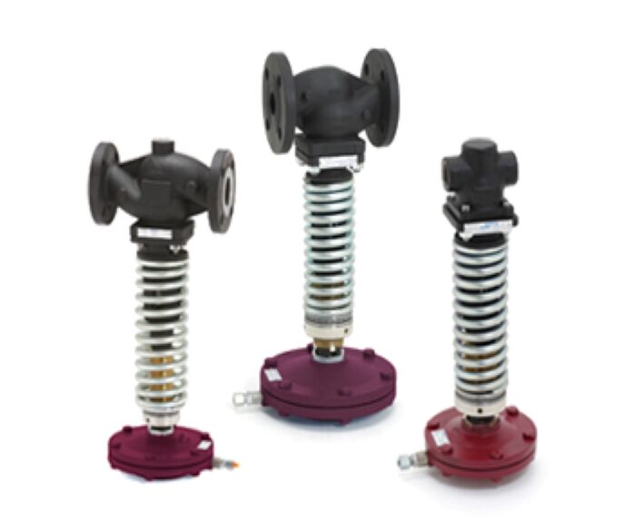
The ADCA RP45 series pressure reducing valves are single seated,
bellows sealed controllers that operate without auxiliary energy.
Designed for use with steam, compressed air, and other gases
compatible with the construction.
These valves are particularly suitable for reducing steam pressure in
all energy and process systems where pressures must be kept under
control.
Specially designed high durability bellows, providing pressure
balancing and frictionless plug stem.
Robust construction (fit-and-forget).
Suitable for use with high pressure turndowns.
Interchangeable actuators and adjustment springs.
|
OPTIONS: |
Soft sealing in PTFE/GR for use with steam. Soft sealing in nitrile rubber for use with air and gases. Low-noise flow divider. Sensing pipe on body. |
|
USE: |
Steam, compressed air and other gases compatible with the construction. Limited use with liquids. Consult manufacturer before installing the valve with liquids. |
|
AVAILABLE MODELS: |
RP45G and RP45GT or N – SG iron. RP45S and RP45ST or N – carbon steel. RP45i and RP45iT or N – stainless steel (only available from DN 15 to DN 100). Suffix T: soft sealed with PTFE/GR. Suffix N: soft sealed with nitrile rubber. |
|
SIZES: |
DN 15 to DN 150. |
|
CONNECTIONS: |
RP45G – Flanged EN 1092-2 PN 16. RP45S and RP45i – Flanged EN 1092-1 PN 16 or PN 40. Standard PN 16 DN 65 flanges are supplied with 4 holes. 8 holes, according to EN 1092-1/-2 on request. |
|
AVAILABLE ACTUATORS: |
A1, A10, A11, A12, A3, A4, B1, B3, B4 and C11 – carbon steel. A2, A21, B2 and B21 – SG iron or carbon steel. A1i, A10i, A11i, A12i, A2i, A21i, A3i and A4i – stainless steel. |
|
INSTALLATION: |
Horizontal installation with the actuator vertically, pointing downwards. Installation with the actuator pointing upwards is possible only when the medium temperature is below 90 ºC. The sensing pipe, if not fitted on the valve body, must be installed downstream of the valve at a minimum of 1 meter away or 15 pipe diameters. In steam applications, a “Y” strainer, humidity separator and steam trap should be installed upstream of the valve. |
LIMITING CONDITIONS
|
Valve model |
RP45G RP45S RP45i |
RP45S RP45i |
RP45GT RP45ST RP45iT |
RP45ST RP45iT |
RP45GN RP45SN RP45iN |
RP45SN RP45iN |
|
Body design conditions
|
PN 16
|
PN 40
|
PN 16
|
PN 40 |
PN 16 |
PN 40 |
|
Maximum upstream pressure
|
13 bar
|
25 bar
|
13 bar
|
25 bar |
13 bar |
25 bar |
|
Maximum downstream pressure (DN 15 to 100)
|
13 bar |
18 bar |
13 bar |
18 bar |
13 bar |
18 bar |
|
Maximum downstream pressure (DN 125 and 150)*
|
12 bar |
16.5bar |
12 bar |
16.5 bar |
12 bar |
16.5 bar |
|
Minimum downstream pressure
|
0.15bar
|
0.15bar |
0.15 bar |
0.15 bar |
0.15 bar |
0.15 bar |
|
Maximum operating temperature
|
200ºC |
250 ºC |
200 ºC |
200 ºC |
80 ºC |
80 ºC |
|
Maximum reducing ratio
|
25:1 | 25:1 | 25:1 | 25:1 | 25:1 | 25:1 |
|
Rangeability
|
10:1 |
10:1 |
10:1 |
10:1 |
10:1 |
10:1 |
|
Maximum hydraulic factory valve body test |
24 bar | 60 bar | 24 bar | 60 bar | 24 bar | 60 bar |
*Stainless steel models are not available in these sizes. Remark: Other soft materials and temperature limits on request.
BELFAST CONTROLS EQUIPMENT TRADING L.L.C